
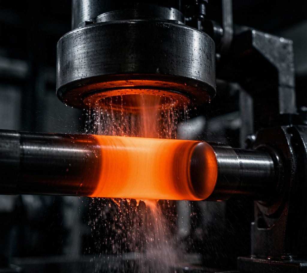
Induction hardening services give a steel part two personalities at once: a glass-hard skin that resists wear and contact fatigue, and a tough, ductile core that absorbs shock without cracking. The trick is heating only the surface, and heating it fast. A copper coil carrying high-frequency alternating current induces eddy currents in the workpiece; those currents concentrate in the outer skin, raising it above the austenitising temperature in a couple of seconds while the core stays comparatively cool. An immediate quench freezes the transformed surface into martensite. The whole cycle on a 40 mm shaft journal takes about eight seconds, and it happens on the shop floor rather than in a furnace batch.

How the Process Works
Frequency selects case depth. High frequency in the 100 to 400 kHz range concentrates current in a very thin skin and produces cases of 0.4 to 1.5 mm, which suits small pins, fine gear teeth, and thin-wall parts. Medium frequency at 3 to 10 kHz drives current deeper and gives 2 to 6 mm cases for heavy shafts, large gears, and rolls. Power density sets how quickly the target depth reaches temperature — too slow and heat conducts inward, defeating the point.
Coil design is where the craft lives. The inductor must mirror the geometry being hardened and hold a consistent air gap, typically 1.5 to 3 mm. Single-shot coils surround the whole feature and heat it at once. Scanning coils traverse along a shaft while a quench ring follows a fixed distance behind, hardening a metre-long journal continuously. Split coils open to allow loading of crankshafts and other awkward shapes.
Quenching follows within a fraction of a second, usually with a polymer-water solution sprayed through the coil housing or a following ring. Polymer concentration is tuned to cool fast enough for full martensite formation but slowly enough to limit thermal shock and quench cracking. Almost every induction-hardened part is then low-temperature tempered at 150 to 200 °C to relieve stress and restore a little toughness, at the cost of two or three Rockwell points.
Induction vs Carburising, Nitriding and Through Hardening
Carburising diffuses carbon into a low-carbon steel over many hours in a furnace, then quenches the whole part. It produces excellent deep cases and is the standard for automotive transmission gears, but the cycle is long, distortion is significant, and the entire part is heated. Our overview of heat treatment services compares the furnace routes in full.
Nitriding runs at 500 to 570 °C, below the transformation temperature, so distortion is minimal and no quench is needed. It gives a very hard but thin case, typically under 0.5 mm, and takes 20 to 90 hours. It is the right answer for precision dies and pre-finished components that cannot be reground.
Through hardening makes the whole section hard, which is fine for tools and springs but leaves a structural part brittle. Induction hardening sits between these: selective, fast, low-distortion, and applied only where wear occurs. A splined shaft can have hardened splines and a soft, machinable centre section on the same part — something no furnace process can achieve without masking.
There is also a fatigue benefit that is often overlooked. The martensitic case occupies more volume than the parent structure, so it locks the surface into compressive residual stress. That compression must be overcome before a fatigue crack can start, which is why induction-hardened shafts routinely show 30 to 50 percent higher bending fatigue limits. The same physics underpins shot peening services, and the two are sometimes combined on highly stressed components.
Which Steels Respond
The process needs enough carbon to form martensite. Below about 0.30 percent carbon there is not enough, and hardness will disappoint. The reliable range is 0.35 to 0.55 percent carbon.
Medium-carbon plain steels 1040, 1045, and 1050 harden to 55 to 60 HRC and are the most common and most economical choice. Alloy steels 4140, 4340, and 5140 reach 55 to 62 HRC with better hardenability, meaning a deeper and more uniform case on thick sections. Cast irons — grey, ductile, and austempered — respond well provided the matrix is pearlitic, and hardened cam lobes and cylinder liners are standard applications. Bearing steel 52100 and tool steels can be induction hardened where selective treatment is required.
What will not work: low-carbon steels such as 1018 and 1020, austenitic stainless steels, aluminium, copper, brass, and any non-ferrous alloy. Parts made from those materials need a different wear strategy — chrome plating, nitriding, or a thermal spray overlay.
Pre-hardening condition matters more than most buyers expect. A quenched-and-tempered starting structure gives a finer, more uniform response than an annealed or normalised one, because carbides dissolve faster in the short heating cycle. We commonly specify Q&T bar stock for shafts that will be induction hardened, then rough machine on CNC turning centres before treatment.
Case Depth, Distortion and Finishing
Effective case depth is defined at 50 HRC or at 80 percent of surface hardness, and it must be specified on the drawing along with the hardness range and the exact zone to be hardened. Under-specifying case depth on a gear tooth causes case crushing at the root; over-specifying wastes energy and increases distortion. A useful starting rule for gear teeth is a case depth of 20 to 25 percent of the tooth thickness at the pitch line.
Distortion is small compared with furnace hardening but never zero. Shafts typically bow 0.05 to 0.20 mm per metre. Long slender parts may need straightening after treatment. Bores tend to shrink slightly. Because of this, critical diameters are machined with grinding stock and finished afterwards on cylindrical grinding or centerless grinding machines. Leaving 0.2 to 0.4 mm of stock on diameter is normal practice, and our notes on precision shaft manufacturing set out the full machining sequence.
Sharp corners, keyways, cross-holes, and abrupt section changes concentrate the induced current and overheat locally, which is the most common cause of quench cracking. Generous radii and, where possible, keeping the hardened zone away from cross-holes solves it. If the geometry cannot be changed, we adjust coil design and power profile to compensate. Verification is by surface hardness testing, sectioned microhardness traverse on a sample, magnetic particle inspection for cracks, and etch-pattern checking of the hardened zone boundary. Additional operations such as shot peening or supplementary heat treatment can be sequenced in-house, alongside the wider range of finishing shown under metal other parts.
Frequently Asked Questions
How hard can induction hardening get? 55 to 62 HRC on medium-carbon and alloy steels, and 50 to 58 HRC on ductile iron. Achievable hardness is set almost entirely by carbon content, not by the process.
Can you harden only part of a component? Yes, and that is the main reason to choose induction. Coil geometry and scan travel define the zone precisely, with a transition band of a few millimetres. Threads, bearing seats, and weld areas can be left soft.
How much distortion should I allow? Plan for 0.05 to 0.20 mm per metre of bow on shafts and slight bore shrinkage. Leave grinding stock on all critical diameters and specify straightness after hardening rather than before.
Is induction hardening cheaper than carburising? Per part, usually yes at moderate to high volume — cycle times are seconds rather than hours, and no protective atmosphere is required. Carburising remains more economical for large furnace batches of small parts needing deep cases.
Can hardened parts be welded or machined afterwards? Welding into or near the hardened zone will temper it back and is not recommended. Machining requires carbide or CBN tooling, and grinding is generally preferred. Plan all conventional machining before hardening.
What should the drawing specify? Material grade and pre-hardening condition, the hardened zone shown graphically, surface hardness range in HRC, effective case depth with its measurement criterion, tempering requirement, and any straightness or crack-inspection call-out. Send that with your model and we will confirm feasibility and price within 24 hours.
Ready to Start Your Project?
Get a build-ready quote on your custom metal parts within 24 hours. Share your drawing and our engineers will respond with process, lead time, and pricing.