
Robotics & Automation Parts Manufacturing: Precision Components for Industrial Robots and Automated Systems
Complete guide to manufacturing precision metal components for industrial robots and automation systems. From robot arm joints and end effectors to custom frames and mounting hardware.
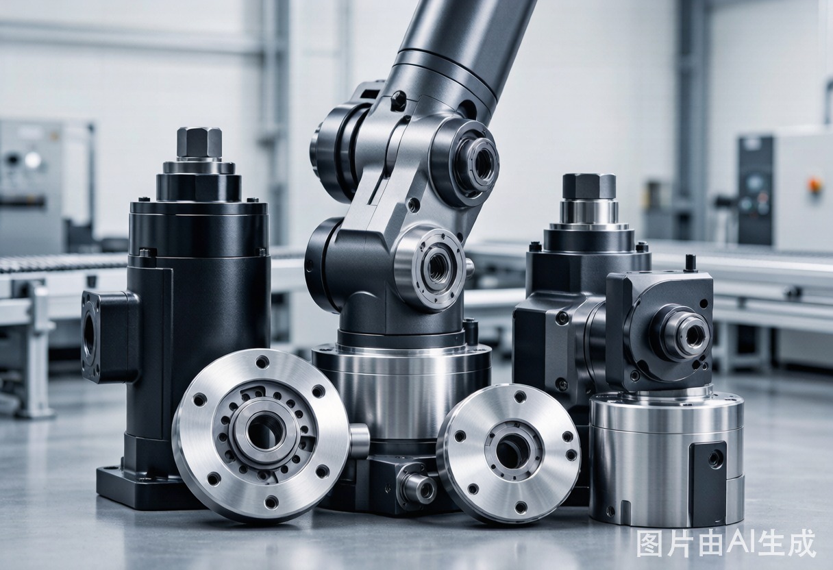
Table of Contents
- 1. The Robotics Manufacturing Landscape: What Makes Robot Parts Different
- 2. Robot Arm Components: Joints, Links & Structural Parts
- 3. End Effectors & Grippers: Custom Tooling for Every Application
- 4. Robot Frames & Base Structures
- 5. Motion Control Components: Gears, Shafts & Bearings
- 6. Sensor & Vision System Mounting Hardware
- 7. Process Selection Matrix: Robotics Components
- 8. Material Selection for Robot Parts
- 9. Design for Manufacturing: Robotics Edition
1. The Robotics Manufacturing Landscape: What Makes Robot Parts Different
Robotics is one of manufacturing’s fastest-growing sectors — the global industrial robot market exceeded $18 billion in 2025 and is projected to grow at 12% CAGR through 2030. Behind every robot arm are hundreds of precision metal components, each requiring specific manufacturing processes to balance accuracy, stiffness, weight, and cost.
Robotics parts sit at a unique intersection: they demand precision approaching aerospace levels (±0.01mm for joint interfaces), but at cost structures closer to automotive. Unlike aerospace’s “certify everything” approach, robotics manufacturing rewards smart process selection that achieves required precision without unnecessary cost. A robot arm link that costs $2,000 to manufacture makes economic sense; the same link at $8,000 (aerospace pricing) kills the product.
Key Robotics Manufacturing Requirements
- Weight optimization: Every gram on the end of a robot arm multiplies the torque requirement at the base. Lightweight designs directly reduce motor and gearbox costs.
- Stiffness-to-weight ratio: A 0.1mm deflection at the end effector translates to 0.5mm+ positioning error. Stiffness is non-negotiable.
- Duty cycle: Industrial robots run 16–24 hours/day for years. Fatigue life matters for every load-bearing component.
- Volume variability: A robotics startup may need 20 arms for their first field trial, then scale to 500/year, then 5,000/year. The manufacturing process must scale without redesign.
2. Robot Arm Components: Joints, Links & Structural Parts
The robot arm itself is an assembly of links, joints, and housings that must maintain precise geometric relationships while moving at high speeds and carrying payloads.
Joint Housings (Rotary Joints)
Recommended process: CNC Machining from Aluminum Billet (prototype/low-vol), Die Casting + CNC (production)
Joint housings enclose motors, gearboxes, encoders, and bearings while providing the structural connection between arm links. They require precise bearing bores (H7 tolerance), flat mounting faces (0.02mm flatness over 100mm), and threaded holes for assembly. For prototypes and volumes under 200 units/year, 5-axis CNC machining from 6061-T6 or 7075-T6 aluminum billet is the optimal process — zero tooling investment and 2–4 week lead times.
When volumes exceed 2,000 units/year, the economics shift to aluminum die casting + CNC finish machining. The $30,000–60,000 die casting tooling investment is amortized across the production run, reducing per-unit cost from $120–250 (billet CNC) to $35–70 (casting + CNC).
Arm Links (Structural Tubes/Beams)
Recommended process: Aluminum Extrusion + CNC Machining (hollow profile), CNC Machining (solid billet, compact designs)
Robot arm links benefit enormously from aluminum extrusions. A custom extrusion die ($3,000–8,000) produces a hollow profile with internal reinforcing ribs, external mounting grooves, and optimized wall thicknesses. The extrusion is cut to length and CNC-machined at the ends for joint interface features. This approach delivers stiffness comparable to billet machining at 30–50% of the weight and 40–60% of the cost.
For short, compact links where the hollow center provides limited weight savings, direct CNC machining from aluminum billet is often the simpler and faster option. Internal pockets can be machined for weight reduction.
Wrist Components
Recommended process: CNC 5-Axis Machining (all volumes)
The robot wrist is the most complex mechanical assembly in the arm — typically 3 intersecting axes of rotation in a compact envelope. Wrist housings require complex 3D geometries with precision bearing bores at multiple angles. 5-axis CNC machining is the only practical manufacturing method for these components at any volume, given the geometry complexity and precision requirements.
Robot Arm Manufacturing Strategy
- ✓ Prototype (1–50 units): 100% CNC machined aluminum billet — no tooling, iterate fast
- ✓ Pilot production (50–500): Evaluate extrusion for links, keep joints CNC machined
- ✓ Volume production (500–5,000): Die casting for joint housings, extrusions for links
- ✓ High volume (5,000+): Full die casting + automation, consider magnesium for weight-critical applications
3. End Effectors & Grippers: Custom Tooling for Every Application
End effectors are where robots meet the real world. Grippers, welding torches, vacuum pickers, and specialized tooling must be custom-designed for each application — and typically produced in small to medium volumes (10–500 units). This makes process selection fundamentally different from the robot arm itself.
Parallel Gripper Jaws
Recommended process: CNC Machining (steel or aluminum) + Wire EDM (hardened steel gripping features)
Gripper jaws contact the workpiece directly, so they must balance hardness (wear resistance), geometry (to match the workpiece), and weight (to minimize inertia). Typical manufacturing sequence: CNC machine the jaw body from 7075 aluminum or 4140 steel, then wire EDM the gripping surfaces if serrations or complex gripping profiles are needed. For food-grade or cleanroom applications, 304 or 316L stainless steel is specified for corrosion resistance.
Custom End Effector Frames
Recommended process: CNC machining (complex, one-piece), Sheet Metal + Welding (sheet-based designs), or Laser Cutting + Tapping (flat plate assemblies)
End effector frames range from simple flat mounting plates to complex 3D weldments. The process choice depends on geometry:
- Monolithic frames: CNC machined from aluminum billet — maximum stiffness, minimum assembly, ideal for compact designs
- Sheet metal frames: Laser-cut aluminum or steel plates, CNC-bent to shape, TIG-welded into 3D structures — lighter and cheaper than billet for larger frames
- Flat plate assemblies: Waterjet or laser-cut plates bolted together with precision dowel pins — simplest, fastest, easily modified
Quick-Change Tooling Interfaces
Recommended process: CNC Turning + CNC Milling (master/tool plates)
Quick-change systems (ATI, Schunk, Zimmer compatible) require the master plate and tool plate to mate with ±0.01mm concentricity. These are almost always CNC-machined from aluminum or steel, with hardened steel locking balls and cam mechanisms. Surface grinding may be required for the mating faces to achieve the flatness needed for repeatable clamping.
4. Robot Frames & Base Structures
The robot base anchors the entire system. Unlike the moving arm where every gram counts, the base benefits from mass for stability. This fundamentally changes the manufacturing approach.
Robot Base Castings
Recommended process: Sand Casting or Die Casting + CNC Machining
Robot bases are typically cast iron or cast aluminum structures weighing 30–300 kg. Cast iron (GG25/G3000) provides mass for stability and natural vibration damping; aluminum (A356) reduces shipping weight and is preferred for mobile/collaborative robots. After casting, CNC machining creates the precision mounting surfaces for the robot arm, cable pass-throughs, and leveling feet interfaces.
Welded Steel Bases (Custom Automation)
Recommended process: Laser Cutting + MIG Welding + Stress Relief + CNC Machining
For custom automation cells rather than standard robot models, welded steel bases offer flexibility. Steel plates are laser-cut with interlocking tab-and-slot features for self-fixturing, then MIG-welded. Post-weld stress relief (thermal treatment at 600°C for 2 hours) prevents distortion during subsequent CNC machining of mounting surfaces. The result: a custom base for $3,000–12,000 versus $15,000–40,000 for a custom casting with 8–12 week lead time.
Aluminum Profile Frames (Collaborative/Lightweight Robots)
Recommended process: Aluminum Extrusion (standard profiles) + CNC Machined Brackets
Collaborative robots (cobots) and light industrial robots increasingly use aluminum T-slot extrusion profiles for structural frames. Standard 45x45mm, 45x90mm, or 80x80mm profiles are cut to length and joined with CNC-machined aluminum corner brackets. This approach requires zero tooling, can be reconfigured, and is ideal for system integrators building one-off automation cells.
Base Structure Decision Matrix
- ✓ Standard robot model, >100 units/year → Cast iron or aluminum casting
- ✓ Custom automation cell, 1–10 units → Welded steel fabrication
- ✓ Lightweight cobot, <50 units/year → Aluminum extrusion frame
- ✓ Need minimum vibration → Cast iron + epoxy-granite fill for damping
- ✓ Weight-critical mobile robot → Aluminum casting + topology-optimized CNC machining
5. Motion Control Components: Gears, Shafts & Bearings
While most robotics companies buy standard bearings and gearboxes (Harmonic Drive, Nabtesco, etc.), there is growing demand for custom motion control components, especially in cost-sensitive applications and specialized robots.
Custom Gears (Timing Pulleys, Spur Gears)
Recommended process: CNC Hobbing (production), Wire EDM (prototype), or Powder Metallurgy (high volume >20K)
Timing pulleys for synchronous belt drives in robot joints are typically CNC-turned and then hobbed or gear-shaped. For small-lot prototypes, wire EDM can cut gear profiles directly, eliminating the hobbing tool cost. At very high volumes, powder metallurgy sintered gears offer the lowest unit cost but require $8,000–20,000 in compaction tooling.
Precision Shafts & Axles
Recommended process: CNC Turning + Cylindrical Grinding
Robot joint shafts require bearing-fit diameters with h6 or tighter tolerances and surface finishes of Ra 0.2–0.4μm. CNC turning achieves the rough geometry; cylindrical grinding achieves the final precision. For shafts under 25mm diameter, centerless grinding provides the best concentricity and surface finish at the lowest cost for medium-to-high volumes.
Harmonic Drive Components (Flexsplines, Circular Splines)
Recommended process: CNC Hobbing/Turning + Heat Treatment + Grinding
The flexspline (the thin-walled cup with external gear teeth that deforms elastically) is one of the most challenging parts to manufacture in robotics. It requires precision gear cutting on a thin-walled cup that is inherently flexible. Manufacturing involves: CNC turning the cup blank from alloy steel, gear cutting (hobbing or gear shaping), heat treatment to 50–55 HRC, and finish grinding of the bearing surfaces. This is a specialty manufacturing capability that few general machine shops possess.
6. Sensor & Vision System Mounting Hardware
Modern robots are sensor-rich. Each sensor needs precisely positioned mounting hardware — and the accuracy of the mounting directly affects sensor data quality.
Camera & LiDAR Mounts
Recommended process: CNC Machining (aluminum) ± Sheet Metal (steel brackets)
Vision system mounts require angular accuracy of ±0.05° for stereo camera pairs. CNC-machined aluminum mounts with precision dowel pin locations achieve this. For lower-accuracy applications (single camera, LiDAR), laser-cut and CNC-bent sheet metal brackets are cost-effective at half the price.
Force/Torque Sensor Adapters
Recommended process: CNC Machining (stainless steel or aluminum)
Force/torque sensors (ATI, Robotiq, OnRobot) require rigid mounting adapters that transmit forces without deformation. Stainless steel (17-4PH or 304) adapters are CNC-machined with ground flat mounting faces for maximum stiffness and zero hysteresis in force measurement.
7. Process Selection Matrix: Robotics Components
| Component | Prototype (1–50) | Pilot (50–500) | Production (500+) | Material |
|---|---|---|---|---|
| Joint Housing | CNC 5-Axis Al | CNC 5-Axis Al | Die Casting + CNC | 6061-T6 / A380 |
| Arm Link (long) | CNC + Weld Fab | Al Extrusion + CNC | Al Extrusion + CNC | 6061-T6 / 6082-T6 |
| Wrist Housing | CNC 5-Axis Al | CNC 5-Axis Al | CNC 5-Axis (automated) | 7075-T6 / 6061-T6 |
| Gripper Jaw | CNC + Wire EDM | CNC + Wire EDM | CNC + Induction Hardening | 4140 / D2 / 7075 |
| End Effector Frame | CNC / Laser+Bend+Weld | CNC / Laser+Bend+Weld | Laser+Bend+Weld | 6061-T6 / Mild Steel |
| Quick-Change Plate | CNC Turn + Mill | CNC Turn + Mill | CNC Turn + Mill | 7075-T6 Al |
| Robot Base | Welded Steel + CNC | Welded Steel + CNC | Sand Casting + CNC | GG25 Iron / A356 Al |
| Timing Pulley | Wire EDM / CNC | CNC Hobbing | CNC Hobbing | 1045 Steel / 7075 Al |
| Precision Shaft | CNC Turn + Grind | CNC Turn + Grind | CNC Turn + Centerless Grind | 4140 / 440C SS |
| Camera Mount | CNC Alum | CNC Alum | Laser+Bend Sheet Metal | 6061-T6 / Steel |
| Force Sensor Adapter | CNC SS | CNC SS | CNC SS | 17-4PH / 304 SS |
| Cable Management | 3D Print / CNC | Sheet Metal + Powder Coat | Injection Mold + Extrusion | Nylon / Steel / Al |
8. Material Selection for Robot Parts
| Material | Best For | Key Advantage | Weight Factor | Relative Cost |
|---|---|---|---|---|
| 6061-T6 Aluminum | Links, housings, frames | Balanced strength, cost, machinability | Light (2.7 g/cm³) | 1x |
| 7075-T6 Aluminum | High-stress joints, end effectors | Strength comparable to mild steel | Light (2.81 g/cm³) | 1.5x |
| A356 Cast Aluminum | Base castings, large housings | Castability, medium strength | Light | 0.7x |
| 4140 Alloy Steel | Shafts, gears, gripper jaws | Hardenable to 55 HRC | Heavy (7.85 g/cm³) | 1.5x |
| 17-4PH Stainless | Force sensors, cleanroom parts | Corrosion + high strength | Heavy | 3x |
| 304 Stainless | Food-grade grippers, washdown | FDA-compatible, weldable | Heavy | 2x |
| Cast Iron GG25 | Robot bases, machine frames | Vibration damping + mass | Very heavy | 0.4x |
| Carbon Steel (mild) | Welded frames, brackets | Lowest cost, weldable | Heavy | 0.3x |
9. Design for Manufacturing: Robotics Edition
Good DFM decisions at the design stage can cut manufacturing costs by 30–60% without sacrificing performance. Here are robotics-specific DFM principles:
1. Design for the Process You Will Actually Use
If your volumes will be 50–200 units/year, design for CNC machining, not die casting, even if die casting seems “more professional.” A CNC-optimized design with accessible tool paths, standard corner radii (not sharp internal corners), and generous pocket depths will cost less than a casting-optimized design forced into CNC machining.
2. Minimize Setups
Every CNC setup (flipping and re-fixturing the part) adds cost and reduces accuracy. Design parts to be machinable in 1–2 setups where possible. A 5-axis-optimized part machined in one setup will be more accurate and 20–40% cheaper than the same geometry requiring 4 setups on 3-axis machines.
3. Standardize Fastener Interfaces
Every unique thread size and fastener type in your robot assembly adds cost: tool changes for machining, inventory SKUs, assembly tooling. Standardize on 2–3 thread sizes (e.g., M3, M5, M8) across the entire robot. The minor material inefficiency of slightly oversized fasteners is dwarfed by the procurement and assembly savings.
4. Separate Precision Features from Structural Features
A robot link does not need ±0.01mm precision across its entire length — only at the joint interface surfaces. Design with precision-machined bosses or pads only where needed, leaving the surrounding structure at standard tolerances. This is the single most powerful cost-reduction technique in robot part design.
Checklist Before Sending Your Robotics Part to Manufacturing
- ✓ All internal corner radii match standard end mill sizes (≥R3mm for aluminum, ≥R5mm for steel)
- ✓ Thread depths ≤ 2.5x diameter (deeper threads are disproportionately expensive)
- ✓ Flat-bottom holes avoided (standard drill point angles: 118° or 135°)
- ✓ Wall thickness ≥ 2mm for aluminum, ≥ 1.5mm for steel (thinner walls require delicate machining)
- ✓ Tolerances specified only on functional features — not blanket ±0.05mm on the entire drawing
- ✓ Material grade and heat treatment condition explicitly specified (e.g., 6061-T6, not just “Aluminum”)
Ready to Start Your Project?
Our engineering team will respond within 24 hours with a detailed quotation.