
Metal injection molding (MIM) turns metal powder and binder into near-net-shape parts that would take many CNC operations to machine from solid. It is a powerful process, but only when the part is designed for it. This metal injection molding design guide covers the rules that separate a cheap, repeatable MIM part from one that distorts, cracks, or blows the tooling budget.
When MIM Is the Right Process
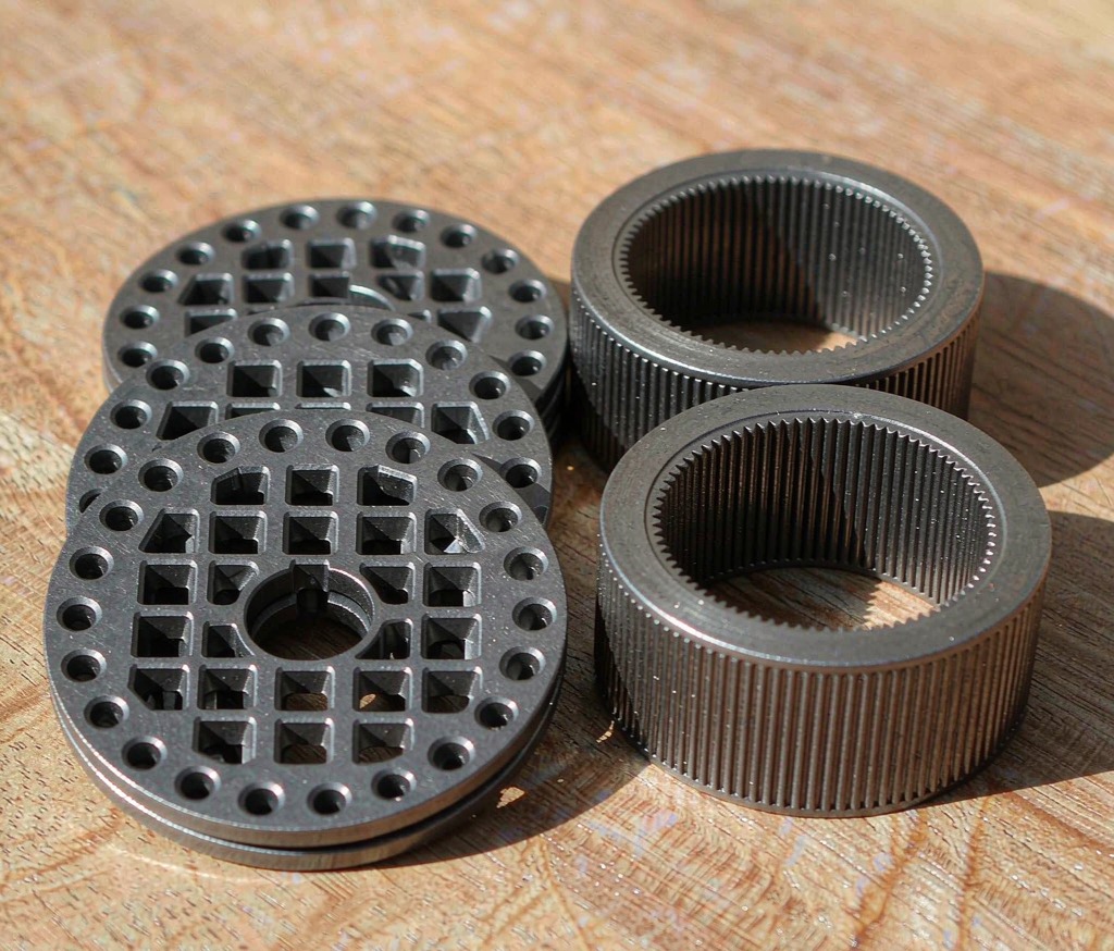
MIM fits small, complex, high-volume parts—typically under about 150 g—where machining would need multiple setups or cannot reach internal features. Think surgical instruments, firearm components, connector housings, and miniature gears. Our MIM injection molding process forms the green part; MIM sintering then densifies it to near-full strength. If the part is large, simple, or needed once, MIM is the wrong tool.
The economic tipping point is volume. Below a few thousand pieces, machining or printing usually wins because MIM’s tooling cost cannot be spread. Above that, MIM’s near-net-shape advantage compounds: every machined feature you eliminate is recurring labor and scrap you no longer pay for, on every single part, forever. That is why MIM dominates in industries that ship the same small complex part by the million.
Wall Thickness and Uniformity
Keep walls between roughly 1 mm and 4 mm and as uniform as possible. Thick sections sinter slower and can warp or develop density gradients; thin sections may not fill. Variation should stay within about ±25 percent of nominal. Uneven mass is the most common cause of distorted MIM parts, so design for balanced flow from the gate outward.
If a feature truly needs a thick section, consider molding it slightly oversize and machining the excess after sintering rather than fighting the shrinkage. Ribs should be about 60 percent of the adjacent wall, not equal or thicker, to avoid competing masses that pull the part out of shape. Designing for uniform shrinkage up front is far cheaper than straightening distorted parts later.
Corners, Draft, and Undercuts
Radius every internal corner—a minimum of 0.3 mm, preferably 0.5 mm—because sharp corners crack during debinding and sintering. Add draft of at least 0.5° on external walls and 1.0° internally so the fragile green part ejects without breaking. Avoid undercuts: each side action adds 15–35 percent to tool cost. Redesign an undercut as a feature that can be machined later if it is truly needed.
Tolerances and Shrinkage
MIM shrinks 14–18 percent linearly during sintering, so the mold is cut oversize by a compensation factor tuned to the material. As-sintered tolerance is about ±0.3 to ±0.5 percent; tighter dimensions need post-sinter machining. Mark only critical features as tight—over-tolerancing the whole part needlessly raises cost. Plan secondary machining allowance on datum and sealing faces up front.
Shrinkage is also why the first samples matter. The supplier measures actual shrink on trial parts and adjusts the mold before production, because the theoretical factor never matches reality exactly. Budget for a sample iteration in the schedule; skipping it trades a few weeks now for scrap risk across the whole run. A good MIM partner treats first-article data as part of the process, not an optional extra.
Secondary Operations
Most MIM parts need some finish work. Deburring cleans parting-line flash, Surface Grinding trues datums, and Heat Treatment can follow for hardness. Cosmetic or corrosion needs are met by Powder Coating or plating. Decide these before tooling so the green part includes the right stock.
Threaded features deserve special planning. Small molded threads often need a post-mold tap to hit a tight class, while very fine threads may be molded and lightly chased. Agree the thread strategy in the RFQ so the tool and the secondary operation line up. Getting this wrong is a classic source of MIM cost overruns that a short DFM conversation would have caught.
Cost Drivers and RFQ Tips
Tooling dominates first cost; design changes after the steel is cut cost thousands. Relaxing non-critical tolerances, unifying wall thickness, and removing side actions can cut total cost 30–50 percent. In your RFQ, share the 3D model, annual volume, material grade, and which dimensions are critical. Compare MIM against casting in our Investment Casting Guide and against volume strategies in Metal Contract Manufacturing and Low Volume Manufacturing.
One more cost lever is secondary work. Every feature that must be machined, drilled, or threaded after sintering adds recurring operations. If a hole can be molded to size or a thread tapped in a simple post step, design for it. The cheapest MIM part is the one whose as-sintered shape already does most of the job, with only the truly critical surfaces finished—exactly the balance a DFM review is meant to find before tooling is committed.
Frequently Asked Questions
What size parts suit MIM?
Small, complex parts up to roughly 150 g. Larger or simpler parts are better machined, cast, or stamped.
How tight can MIM tolerances be?
As-sintered about ±0.3–0.5 percent. Tighter dimensions need post-sinter machining with stock allowed.
Why radius all internal corners?
Sharp corners crack during debinding and sintering. A small fillet dramatically improves yield.
Is MIM cheaper than CNC?
At volume, yes, because it near-net-shapes complex geometry. For low quantities, CNC is usually cheaper.
What materials work for MIM?
Stainless steels, low-alloy steels, titanium, and some specialty alloys are common MIM feedstocks.
When should I avoid undercuts?
Almost always—each side action adds major tool cost. Redesign or machine the feature later.
Ready to Start Your Project?
Send us your drawings and requirements. Our engineering team will review manufacturability and return a competitive quote with realistic lead time—usually within 1–2 business days.