
A caliper tells you a dimension. A coordinate measuring machine tells you whether the part conforms. That difference matters the moment a drawing carries position, profile, or runout callouts, because those tolerances are defined relative to datums and cannot be evaluated with hand tools. CMM inspection services turn a pile of measurements into a defensible statement that the part meets the print.
This guide explains what CMM inspection actually proves, which machine type fits which part, how datums and GD&T are verified correctly, what belongs in a first article report, and how scanning, uncertainty, and SPC data fit into a supply chain where dimensional disputes cost real money.
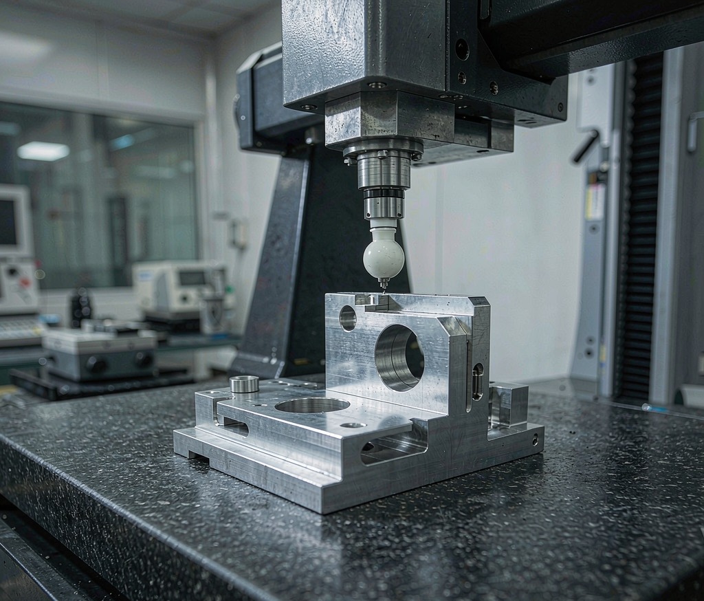
What CMM Inspection Proves
A CMM measures point coordinates in a common reference frame, then fits geometry — planes, cylinders, circles, surfaces — to those points. From that fit it evaluates size, form, orientation, location, and profile against the drawing’s datum structure. That is why a CMM can report true position of a hole pattern or profile of a contoured surface, and a micrometer cannot.
The value in a supply chain is evidentiary. When a part is rejected at incoming inspection, the argument is settled by comparing two measurement reports built on the same datum scheme, not by two people measuring differently. Getting that alignment right depends on the drawing being unambiguous in the first place — the principles in our GD&T guide and our machining tolerances guide are the foundation.
CMM Types and When Each Fits
Bridge CMMs on granite are the workhorses: high accuracy, good throughput, and suited to parts from a few millimetres up to about a metre. Gantry machines handle large fabrications and castings. Horizontal-arm machines are used for sheet metal and body panels where access from the side matters. Portable arms and laser trackers measure parts too large or too fixed to bring to a lab. Vision and optical systems are faster for thin, flat, or very small features.
Probe choice matters as much as machine choice. Touch-trigger probes are accurate and robust for prismatic features. Scanning probes gather thousands of points for form and profile evaluation. Non-contact laser and structured-light sensors capture freeform surfaces quickly but with different uncertainty. For most machined metal parts produced through CNC machining, a bridge CMM with a scanning probe is the right default.
GD&T Verification and Datum Strategy
The single most common inspection error is measuring to a convenient surface instead of the specified datum. If datum A is the large face and B is the bore, the part must be aligned in software using exactly that sequence, or position results will be wrong even when every point is measured accurately. Datum simulation — how the physical part is constrained — must match the drawing intent.
Material condition modifiers change results too. A position tolerance at maximum material condition allows bonus tolerance as the feature departs from MMC, and reporting it as regardless-of-feature-size will reject good parts. Composite profile and pattern controls need the right ordering. Where a drawing is ambiguous, we flag it during DFM support review before parts are cut, which is cheaper than arguing about the report afterwards.
First Article Inspection Reports
A useful first article report is not a dump of numbers. It carries a ballooned drawing where every dimension has a unique number, a table linking each balloon to nominal, tolerance, actual, and pass or fail, plus material certification, process route, and any deviations with disposition. AS9102 defines this structure for aerospace, and its logic is worth borrowing even outside that sector.
The report should also state how the part was constrained, which machine and probe were used, the temperature at measurement, and the software alignment used. Without those, the numbers are not reproducible. Parts we machine and grind in-house are reported against the same datum scheme used to fixture them, which removes a whole category of disagreement — see our precision machined parts guide for how that flows through production.
Scanning, Reverse Engineering, and Deviation Maps
Where a surface is freeform — an impeller vane, a formed panel, a cast contour — point-by-point measurement is not meaningful. Scanning captures dense point clouds that are best-fit to the CAD model and reported as a colour deviation map, immediately showing where the part is high or low and by how much. This is the only sane way to inspect stretch-formed or cast contours.
The same data supports reverse engineering when a legacy part has no model. Scanned geometry is converted to surfaces and then to a parametric model that can be manufactured and revised. That workflow, including how to handle worn and damaged originals, is covered in our reverse engineering guide, and it is offered directly through our reverse engineering service.
Measurement Uncertainty and Gauge Capability
Every measurement has uncertainty, and it must be small relative to the tolerance being judged. A common rule is that the measurement system should consume no more than ten percent of the tolerance band; twenty percent is often accepted. Measuring a ±0.005 mm feature on a machine with 0.004 mm uncertainty is not inspection, it is guessing.
Uncertainty comes from machine accuracy, probe configuration, part fixturing, temperature, and operator method. Labs control it by holding 20 °C ±1 °C, calibrating with certified artefacts, and running gauge repeatability studies. Ask any inspection supplier for their calibration certificate and their stated uncertainty for the feature class you care about — a supplier who cannot answer is not measuring, they are reporting.
In-Process Control and SPC Data
First article inspection proves the process can make a good part; statistical process control proves it keeps doing so. Sampling key features across a run and charting them reveals tool wear, thermal drift, and fixture movement before parts go out of tolerance. Capability indices such as Cp and Cpk turn that into a number your quality team can act on.
In practice we select two to five critical features per part for in-process CMM sampling, chart them, and set reaction limits inside the tolerance band. Features produced by CNC milling and surface grinding are the usual candidates because they are the tightest and the most sensitive to tool condition. Data can be delivered as CSV or in your supplier portal format.
Cost Drivers and Turnaround
Inspection cost is driven by the number of controlled features, programme complexity, fixturing needs, and sample size — not by part size. A part with 30 ballooned dimensions costs several times one with 8. Reducing over-tolerancing on non-functional features is the fastest way to cut inspection cost, and it usually improves manufacturability too.
Typical turnaround: 1–3 days for a first article report on an existing programme, 3–5 days including programme development and fixturing for a new part, and same-day for expedited in-process checks. Send the drawing with GD&T, the 3D model, the sample quantity, and the report format you need — AS9102, PPAP, or your own template. If material questions are open as well, material consulting can be run in parallel.
Frequently Asked Questions
What accuracy can your CMMs achieve?
Bridge CMMs in a temperature-controlled lab deliver volumetric accuracy in the low micron range, typically around 1.8 + L/350 µm. We state uncertainty for the specific feature class in the report.
Do you provide AS9102 first article reports?
Yes. We supply ballooned drawings with Forms 1, 2, and 3, material and process certifications, and disposition of any nonconformance.
Can you inspect parts you did not manufacture?
Yes. Standalone inspection is available for customer-supplied parts, including incoming verification and dispute resolution against a supplier’s report.
How do you handle freeform surfaces?
We scan them and report a best-fit colour deviation map against your CAD model, plus point measurements at any locations you specify.
Do you offer reverse engineering from a physical sample?
Yes. We scan the part, build surfaces, and deliver a parametric CAD model suitable for manufacturing, with a deviation report showing how closely the model matches the original.
What information do you need to quote inspection?
The drawing with GD&T, the 3D model, the number of features to be reported, sample quantity, and the report format required. Fixturing needs are assessed from the geometry.
Ready to Start Your Project?
Get a build-ready quote on your custom metal parts within 24 hours. Share your drawing and our engineers will respond with process, lead time, and pricing.